AISC
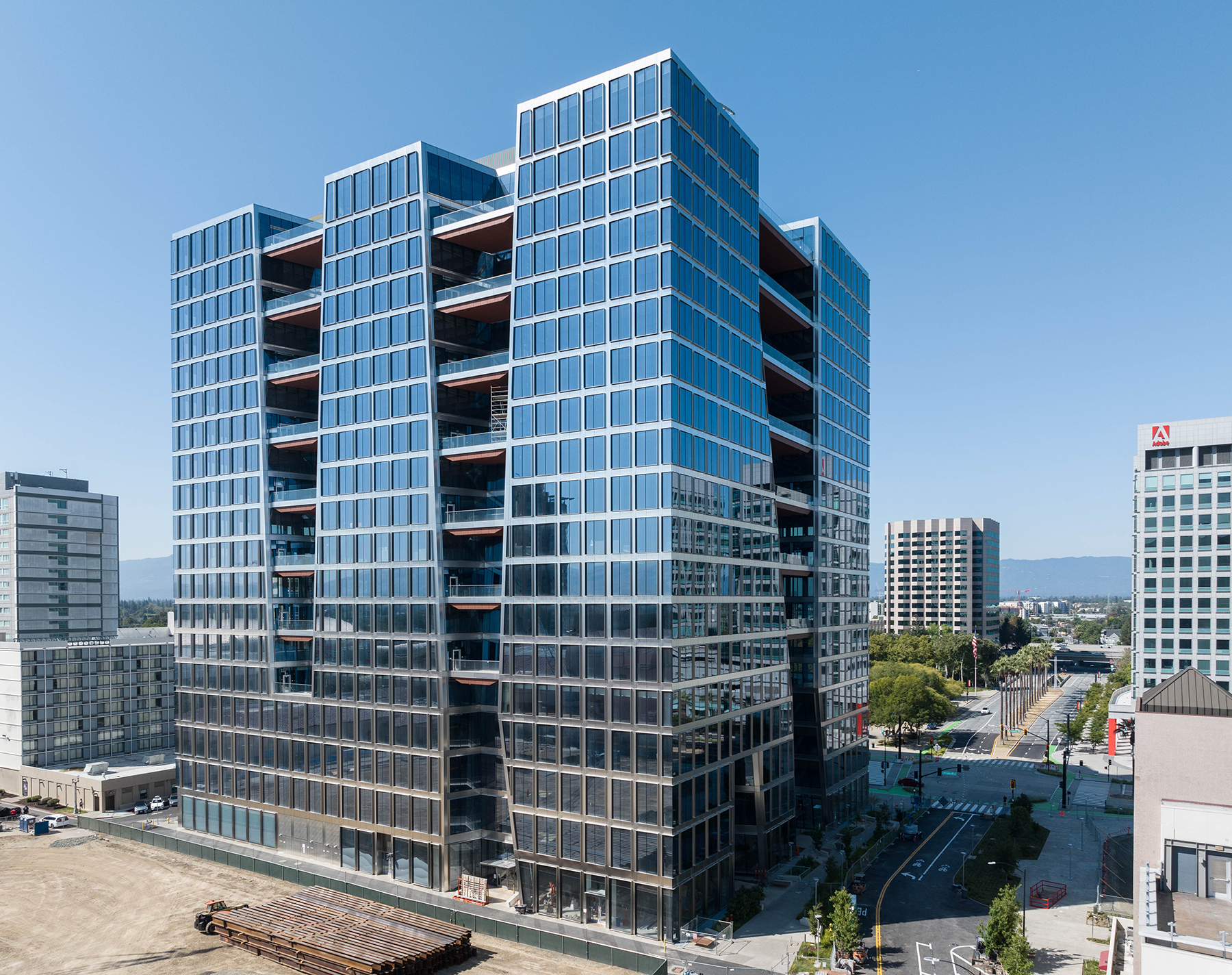
200 Park
Excellence in Constructability
"The SpeedCore system really set 200 Park apart in constructability. SpeedCore offers schedule efficiency and reduction of fireproofing based on the system thickness. More importantly, it offers a reduced level of high-risk safety activities associated with traditional concrete cores, because the preassembled steel frames are prefabricated and sequentially installed versus a concrete core rising in advance of the steel sequences." -- Rob Martinelli, Senior Vice President, Operations, Pepper Construction, 2025 IDEAS² Awards Judge
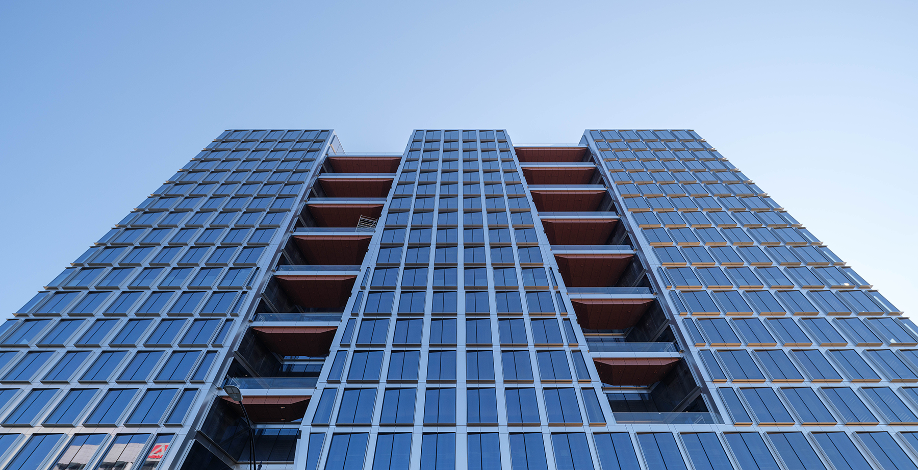
The tallest building in San Jose, Calif., is also the state’s first of its kind. The 19-story, 300-ft office tower known as 200 Park became the first California building--and second anywhere--to use the SpeedCore structural system when steel erection began in 2021.
Steel was the unquestioned choice to achieve the building’s open layout, which includes outdoor terraces on about half the levels and natural light pathways at almost every turn. SpeedCore emerged from the project team’s studies and early considerations as more cost-effective than a traditional braced frame or reinforced concrete core. SpeedCore could also be erected faster--three months faster than a traditional reinforced concrete core. Additionally, its substantial shear capacity reduced wall thickness by up to 18 in. (up to 30%) compared to a concrete core wall.
The $500 million building’s framing system has 10,000 tons of structural steel. The tower’s SpeedCore system--also known as composite steel plate shear wall/concrete-filled (C-PSW/CF)--accounts for roughly 4,000 tons of the total steel package. All told, it features nearly 1 million sq. ft of technology-driven Class A office space, four underground parking levels, ground-level retail, a 20,000-sq.-ft fitness center, and three above-ground stacker parking levels that can be converted into office space. Its oversized floor plates average more than 54,000 sq. ft--twice the size of typical San Jose office buildings.
Two-story outdoor terraces create light canyons that allow natural light to travel deep into each floor while providing desirable outdoor access at each level. The total terrace area exceeds 26,000 sq. ft. The owner and architect wanted the terrace floor framing levels to be as slim as possible, requiring thin custom-tapered shaped beams and girders and sloping steel columns that frame out these openings. Without steel, these key architectural features would not have been economically viable, even though steel is not visible in the final condition.
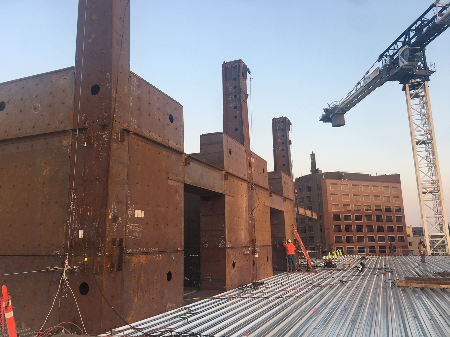
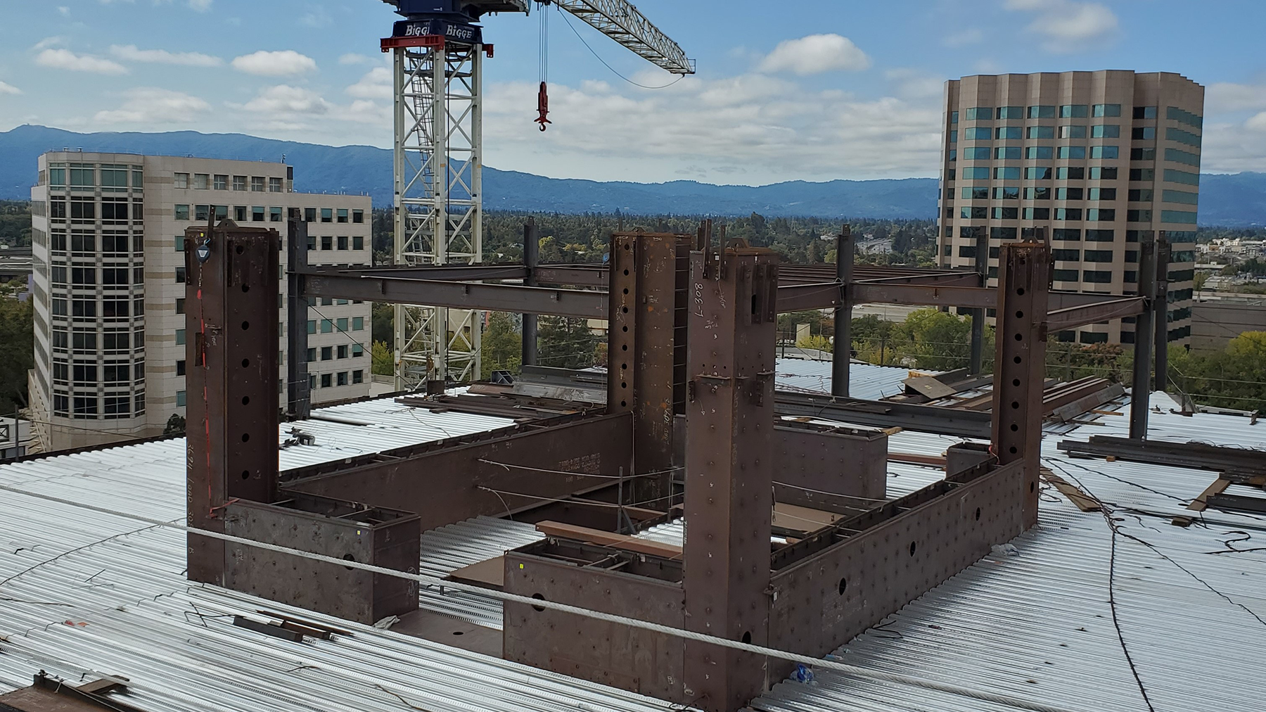
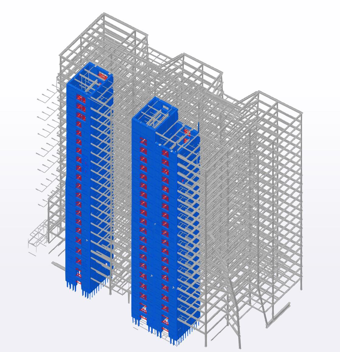
The tower has two composite cores, ranging from 60 ft by 42 ft for the two-cell core and 40 ft by 32 ft for the single-cell core. Nominal wall thicknesses range from 24 in. to 42 in. and decrease in size as the building rises. The heaviest prefabricated core modules weighed more than 17 tons and were about 38 ft long, 14 ft wide, and 3½ ft thick. The cores contain more than 65,000 welded cross ties, and onsite core filling uses a special 10,000-psi grout.
Most of the SpeedCore elements are ASTM A572 Grade 55 plate with a specified limit to control yield strength, helping to ensure the as-fabricated materials closely matched the designers’ performance expectations. The tie rods were designed using weldable 55 ksi round bars. Heavy gravity columns were designed using A913 Grade 65 to help reduce size where possible. The SpeedCore plate is ½ in. thick, and cross ties in the core have a 1-in. diameter.
Unique leaning gravity columns scattered throughout the structure required heavy diaphragm bracing at certain floor levels, which included back-to-back steel angle members configured in a horizontal truss fashion. In some cases, large L10×10×13⁄8-in. angles were used.
Design Savings
While the project was still early in the design process, Purdue University’s Applied Research Institute--which helped create SpeedCore alongside Magnusson Klemencic Associates (MKA) CEO Ron Klemencic--confirmed most fireproofing could be eliminated from the core. The testing showed that walls at least 24 in. thick easily exceeded the three-hour rating. The project team presented the discovery to local building officials and was permitted to eliminate most spray-on fireproofing from the SpeedCore faces, saving the owner additional time and money.
Another pre-fabrication cost-saver was a reduction in through-tie rods within the SpeedCore coupling beams. Additional research and testing at Purdue showed internal headed shear connectors could be used within specific zones on the coupling beam instead of through-tie rods that required connections to each face of core panel. The use of shear connectors simplified the fabrication and assembly of the coupled wall panels.
Research after the design of Seattle’s Rainier Square Tower--the first-ever SpeedCore project--showed designers could reduce overall cross-tie quantities in the SpeedCore panels by increasing the spacing of cross-ties at certain regions of the cores (from 12 in. to 18 in.). This innovation helped lower overall fabrication costs and material quantities, as well as improved constructability.
The 200 Park project was the first time a SpeedCore-type system was used with a partial-height concrete core below grade. The first three basement levels used concrete shear walls before transitioning directly into SpeedCore. Interface with the concrete shear walls below and the significant quantity of reinforcing bars required extensive use of a building information modeling (BIM) approach by the design team and construction trades to ensure the two systems fit as planned.
At the ground level, where base shear is the most demanding, MKA devised a creative way to transfer the large diaphragm loads from the SpeedCore system into the heavy Level 1 concrete slab by using custom built-up plate girder drag elements integrated within the SpeedCore wall and column elements, along with threaded rebar couplers preinstalled to core modules.
About 15 column grids in the gravity-framed system incorporated slanted leaning columns to varying degrees and located at different elevations through the height of the building. Those helped define the light canyons and non-symmetrical building façade features. They introduced some large horizontal loading into the structure that was resolved by a horizontal bracing system located within the depth of the Level 5 framing that could transfer the loads back to the SpeedCore panels. This approach to transferring horizontal forces eliminated the complex interface of a steel-to- concrete or embed-plate construction and differing tolerances.
Constructability from Shop to Site
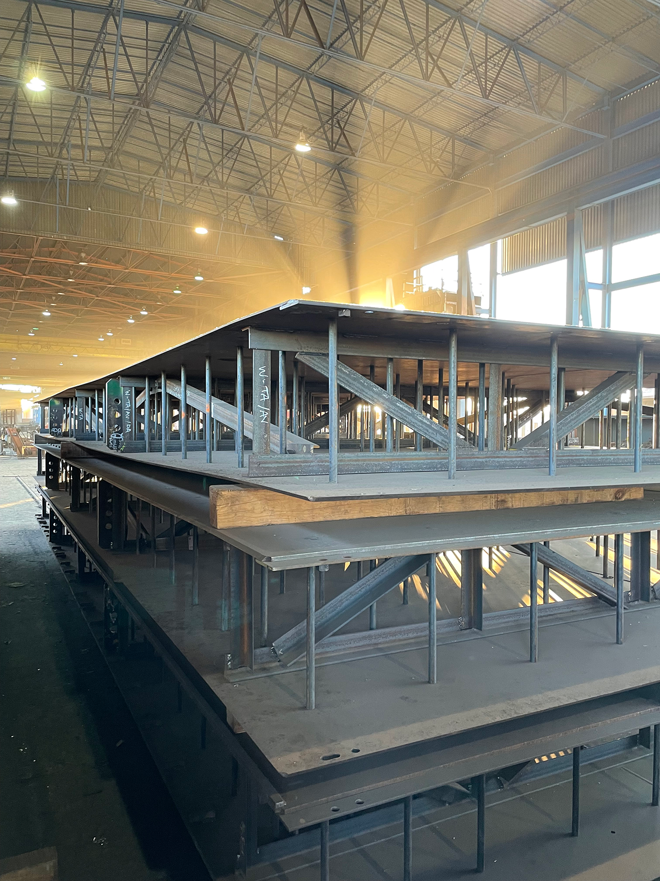
The prefabricated SpeedCore components are large and relatively thin, meaning tight tolerances must be maintained during fabrication to ensure field installation goes quickly and accurately. The fabrication process used specialized fixtures and jigs to help control distortion and ensure accuracy throughout manufacturing. It also required the fabricator to consider numerous operations for handling the oversized steel weldments during transportation to the job site, along with various erection activities before final welding and grouting.
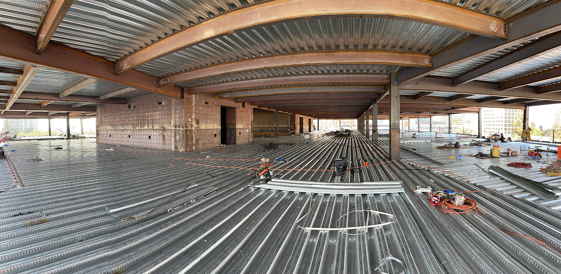
MEP penetrations through the SpeedCore system were critical considerations during the design planning. The location of reinforced sleeved penetrations through the core elements is important to the system’s structural performance and efficient prefabrication before erection and core grouting. Several project stakeholders collaborated during the steel detailing and modeling phases to coordinate the layout and sizes and to ensure MEP designers had necessary passageways without jeopardizing structural performance. The collaborative efforts were rewarded with zero penetration modifications, additions, or location changes.
SpeedCore’s swift erection timeline meant fabricator Schuff Steel needed to maintain a full pipeline of prefabricated core components and surrounding gravity framing to allow both crane hooks to erect steel without interruption. Schuff divided the work among five of its primary fabrication facilities—two produced the SpeedCore elements, while the other three focused on the nonlateral elements.
Schuff worked closely with MKA for all the lower-level specialized SpeedCore elements, which required heavy outrigger drag elements to interface with the core, and developed creative ways to configure them to optimize modularization. Thus, the difficult connections and weld joints could be fully completed in the fabrication shop, and field connections were simple. Schuff also worked with well-known welding expert and engineering consultant Bob Shaw to optimize welds, develop qualified weld procedures, and explore the best options for field welding to mitigate possible shrinkage or distortion in the core.
The building is about three miles from San Jose Mineta International Airport and under a primary flight path, which capped the structure and crane height. After discussion with airport officials, the FAA, general contractor Level 10 Construction, and crane suppliers Bigge Crane and Rigging Company and Bragg Companies, tower cranes were placed at the north and south ends.
An LR1300 crawler crane replaced the north tower crane for erecting the northmost steel on Level 18 through the penthouse. It could boom down in an emergency and be stowed after hours to suit U.S. Standards for Terminal Instrument Procedures (TERPS) requirements. The erection sequence for the north portion of the top two floors, roof, and penthouse left steel out of perimeter bays to allow for a shallower boom angle for erecting the balance of the structure without impacting the overall schedule.
The tower cranes were not freestanding and required lateral support via tie-ins to the primary structure. The structural general notes clearly defined requirements for the state of the structure at the time of tower crane jumps and tie-ins. Specifically, the cores had to be grouted to the level of the tower crane tie-in before any jumping operations. In general, the SpeedCore notes required that the grout within the core walls be placed so that the elevation of the grout is always greater than the elevation of the last poured floor.
To overcome the tie-in challenge and create flexibility, Level 10 Construction engaged erection engineer Simpson Gumpertz & Heger (SGH) to analyze an un-grouted core’s behavior. The results of a detailed finite element analysis of the cores relaxed the constraints so deck pours could occur before the grouting operations for a maximum of one floor, in addition to allowing the tower cranes to be jumped and tied in at a steel framed and decked level, even if the core had not yet been grouted up to that level.
A tight job site meant prefabricated SpeedCore panels were often hoisted directly from the delivery trucks, staged on the working floors, and eventually re-erected into their final position. The extra step required detailed structural analysis from SGH to help ensure local stability and loading on the partially completed framed and decked floors.
All field splices between the SpeedCore elements had to be welded, and the project team developed a plan for welders to stay closely behind the core erection teams to keep the process moving and avoid delays to trades working below.
The building was completed in May 2023, and SpeedCore was the primary reason behind its three-month time savings compared to a traditional frame. It finished a month earlier than the initial SpeedCore schedule. It was speculatively designed, making it an attractive space for a wide tenant range now and in the future.
SpeedCore was also used in Seattle’s Ranier Square office building, which opened in 2021 and shaved 10 months off design and construction time using SpeedCore. In 2023, AISC published Design Guide 38: SpeedCore Systems for Steel Structures (download or order at aisc.org/dg) to help engineers harness SpeedCore’s benefits.
Owner: Jay Paul Company, San Francisco
General contractor: Level 10 Construction, Sunnyvale, Calif.
Architect: Gensler, San Francisco
Structural engineer: Magnusson Klemencic Associates (MKA), Seattle
Steel team:
Fabricator/erector: Schuff Steel Company, Phoenix *AISC full member; AISC-certified fabricator and erector*
Detailer: DBM Vircon, Tempe, Ariz. *AISC associate member*
Erection and construction engineer: Simpson Gumpertz and Heger (SGH), San Francisco
Connections consultant: Steel Structures Technology Center, Inc., Howell, Mich.
- Location: San Jose, CA
- Submitting Firm: Schuff Steel Company
- Photo Credit: 1, 5 - Level 10 Construction (Jason O'Rear); 2, 3, 4, 6, 7 - Schuff Steel